
Folding Robot
Personal Project
Introduction to FR1: P.E.R.R.Y.
(Folding Robot 1: Precision Engineered Robotic Refolding Yunit)
Let's be honest: nobody enjoys folding laundry. That's why I'm building FR1: P.E.R.R.Y., a robotic system designed to tackle the laundry pile for good. This project is a deep dive into modern robotics, integrating mechanical hardware, a custom ROS2-based software stack, and a vision-based AI to solve a real-world problem. Follow along as I document the process of bringing FR1 to life
I am fully aware that I will spend far more time making a robot to fold my clothes than it could ever save me. My disdain for household chores overpowers this.
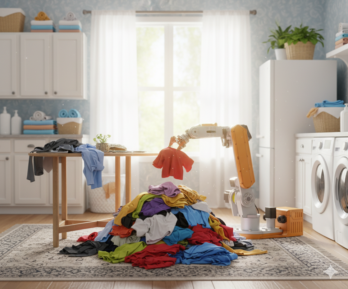
The ultimate goal is a robot that can fully fold any garment. However, the true first step to complete automation is to take a single item from a disorganized pile and unfold it. This is something I have not seen addressed by other people in the automated laundry space.
For the singulation and folding phase, a state machine guides the robot to:
Perceive the Pile: Use the camera mounted on the end of the robot’s arm to view the pile from multiple angles to find the best item to grab.
Pick the Item: Pick the “best” (highest or least occluded) garment from the pile using a gripper with current-based position control to ensure a firm but safe hold.
Unfold and Identify: Place the garment on a workspace and begin a methodical unfolding process. I’m not publishing my strategy in case I manage to secure a $400 million investment from Jeff. After each step, the robot re-evaluates the scene, attempting to classify the item (e.g., t-shirt, towel) until a confidence threshold is met.
The Goal: From Messy Pile to a Fold-Ready State
Hardware
I could spend forever designing and optimizing the arm itself (and be happy doing it), but I need to progress towards the actual goal. I have purchased a robot arm kit (Annin Robotics AR4 mk3), an Intel RealSense D415 depth camera, and designed a custom servo gripper.
Hardware Architecture:
The brain: A powerful desktop PC is used for the development, simulation, and neural network training. The final, untethered system will be deployed on a Raspberry Pi 5. A Teensy 4.1 microcontroller handles low-level motor control.
The eyes: An Intel RealSense D415 depth camera mounted to the robot’s wrist. This provides both an RGB image and a 3D point cloud of the scene.
The arm: An Annin Robotics AR4 MK3. A 6-axis articulated arm that was available as a DIY kit. It delivers more than you'd expect for the price!
The hand: A custom-designed parallel gripper using a Dynamixel XC300 servomotor. The servomotor provides torque feedback, which is essential for setting a limited grip force to prevent tearing clothes.
Assembly and wiring took me some time, mostly because I’m not the best with a soldering iron and what felt like a million 24 AWG signal wires that needed splicing!
Software
The project uses modern ROS2 (Robot Operating System) to create a modular ecosystem of packages to complete specific jobs in harmony. Another bonus of using the Annin AR4 MK3 robot arm was that baseline firmware and software have already been published: ar4_ros_driver. This provided a significant advantage in understanding ROS2 and served as a useful skeleton for further development. I have now developed some custom ROS2 packages to achieve my goals:
fr1_bringup
A top-level package to contain the high-level state machine and launch files that orchestrate the entire system.
fr1_calibration_tools
A collection of first-time setup tools for kinematic and homing calibration
fr1_description
A digital twin with main URDF fr1_robot.urdf.xacro
fr1_driver
Houses the hardware drivers for the Teensy
Adapted from the annin_ar4_driver package. Uses two-phase homing for improved reliability.
fr1_gripper_control
A package to provide a hardware interface for the custom Dynamixel gripper.
fr1_moveit_config
An adaptation of ar4_moveit_config
Uses MoveIt2 and STOMP for smooth, collision-free motion planning
fr1_perception
A package to house the perception pipeline for detecting objects with the RealSense camera.
Project Highlights & Development Log
The sections below contain a bit more technical detail of project challenges, solutions, and milestones.
My baby’s first steps!
Kinematic calibration accounts for slight manufacturing and assembly errors that deviate from the nominal CAD design of the robot. Because this is a serial manipulator with six joints, those slight errors add up.
I am particularly proud of the method developed for kinematic calibration. At first, I tried using the standard robot_calibration package which uses a camera and checkerboard pattern viewed from many different poses to determine the true joint offsets in the robot. Despite weeks of trying, I kept facing configuration issues. I decided to pivot to another method that I implemented myself.
Rather than using the camera, I recalled vaguely how the CMM was calibrated at university: touching a probe to a known reference sphere. However, I don’t exactly have a fancy probe or metrology-grade reference sphere. I managed to find a really pointy old soldering iron tip and 3D printed an adapter for the robot’s flange. I also purchased a 25.02mm ball bearing as the reference sphere. I had the ball bearing rest with a circular line contact on a 3D printed stand so that it could fall off in case I commanded the robot to move too far. By collecting the joint angles at each touch point, a calculation script can optimize the robot's kinematic model. The calculation accounted for inaccuracies in the probe tip position and the location of the sphere. This method was slow and tedious, requiring careful steps to ensure the tip was just barely touching the ball bearing. However, I achieved excellent results after just two iterations with 15 touch point samples in each!
Kinematic Calibration: A CMM-Inspired Approach
Attempting to orbit a point roughly at the tip of the soldering iron prior to calibration.
A linear move after 1 iteration of calibration.
Orbiting a point roughly at the tip of the soldering iron after 2 iterations of calibration.
A linear move after 2 iterations of calibration.
Probe and sphere setup. The extra masking tape helped to corral the sphere when I inevitably knocked it off its stand.
The capture process when trying to use the robot_calibration package.
The Custom Gripper
The gripper control is a fully self-contained Python node. On startup, it performs an automatic calibration routine by using the servomotor's current sensing feature to find its own physical end-stops. The gripper is commanded with current-based position control, meaning it will try to reach the target position unless countered by a specific current (torque). This is useful not only for preventing clothes from tearing but also in situations like an unstable initial grip: if the garment folds or slips slightly when the arm moves, the gripper will tighten rather than stay open.
Further development is required to enhance rigidity and minimize backlash in the rack and pinion gear system.
The gripper’s startup routine and current-based position control demo.
The perception pipeline will leverage AI to interpret the camera's 3D data. The plan avoids the painstaking process of manually labeling thousands of real-world images. Instead, I will use Nvidia Omniverse Replicator to generate a massive, perfectly labeled synthetic dataset of virtual clothing items. This data will be used to train neural networks for two key tasks:
Instance Segmentation: To look at the messy pile and draw a boundary around the single garment that is on top and easiest to grab.
Keypoint Detection: Once a garment is isolated, a second model will find semantically meaningful features like the four corners of a towel or the collar and sleeve-ends of a t-shirt.
Perception Development: Training an AI with Virtual Data
A pile of t-shirts after a simulated drop in Nvidia Isaac Sim.
Testing out the current vision model on a real t-shirt - looks like I’ve got more work to do!
An example of a simulated t-shirt with automatically labelled keypoints and a bounding box.
Testing out the current vision model on a real t-shirt - looks great!