Summer 2019
Airborne Wind Energy Generation
via Crosswind Kites
Scroll ↓
What is Airborne Wind Energy Generation?
The simplest way to describe the concept is that when a kite flies across the wind, it travels much faster than the wind and thus pulls quite hard on its tether. Wrap the tether around a generator while flying an optimized path and you will have a net gain in power. Alternatively, the kite can be affixed with propellers for power generation.
So why this instead of a traditional wind turbine?
Short answer: lower cost per kWh.
Let’s consider a stationary wind turbine: a tall pole with large rotating blades. When wind blows and applies a horizontal load to the turbine, it can be likened to a very large lever. That “tall pole” needs to be increasingly more sturdy the taller it is. Instead, a crosswind kite has a tether loaded purely in tension - meaning the load is not multiplied by a lever arm. This means that a kite can fly at higher altitudes (where the wind carries more energy) with less structural requirements than a traditional wind turbine.

Figure 6 from M. Loyd’s seminal paper on crosswind kite energy
M. L. Loyd, "Crosswind Kite Power," J. Energy, vol. 4, no. 3, pp. 106-111, 1980.

Figure 1: AWESs. Example of Ground-Gen (a) and Fly-Gen (b) AWESs
The Kinetic Intelligence Engineering Department
(Summer 2020)
Working with KISC Founder, Vern Kiss, I designed and built a rugged platform for the future development of the controls system.
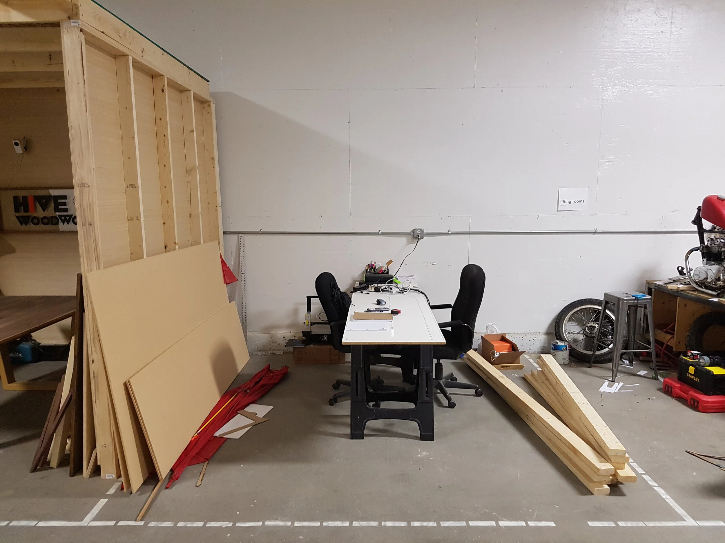
The Start of the Startup
One of my first tasks at Kinetic was setting up the office. We had a 10’ x 10’ plot at the Saskatoon Makerspace to work out of. Conveniently, a Habitat for Humanity ReStore was just up the street from the Makerspace where I was able to frugally source construction materials.
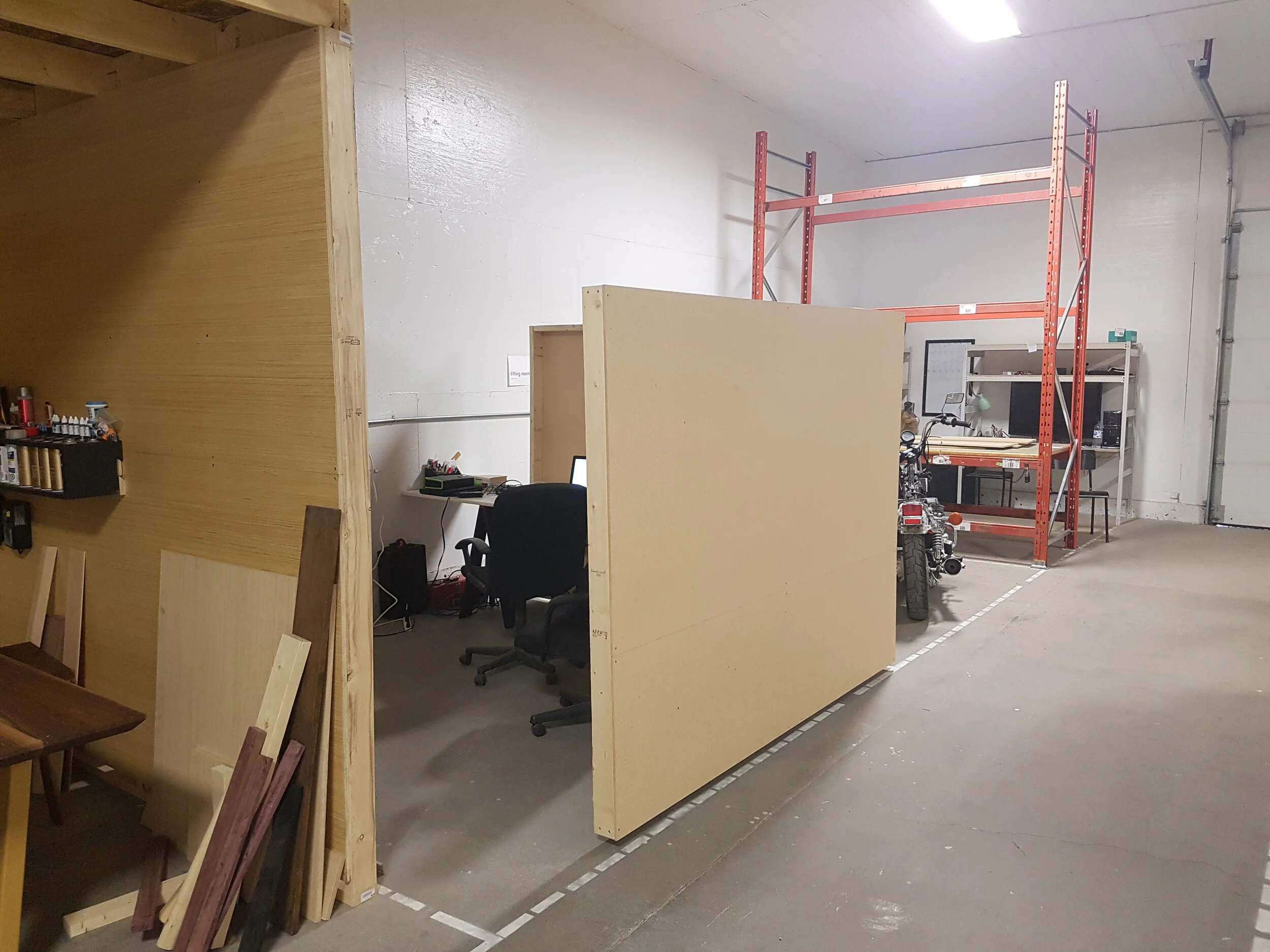
I suppose I could add office design to my resume

Design
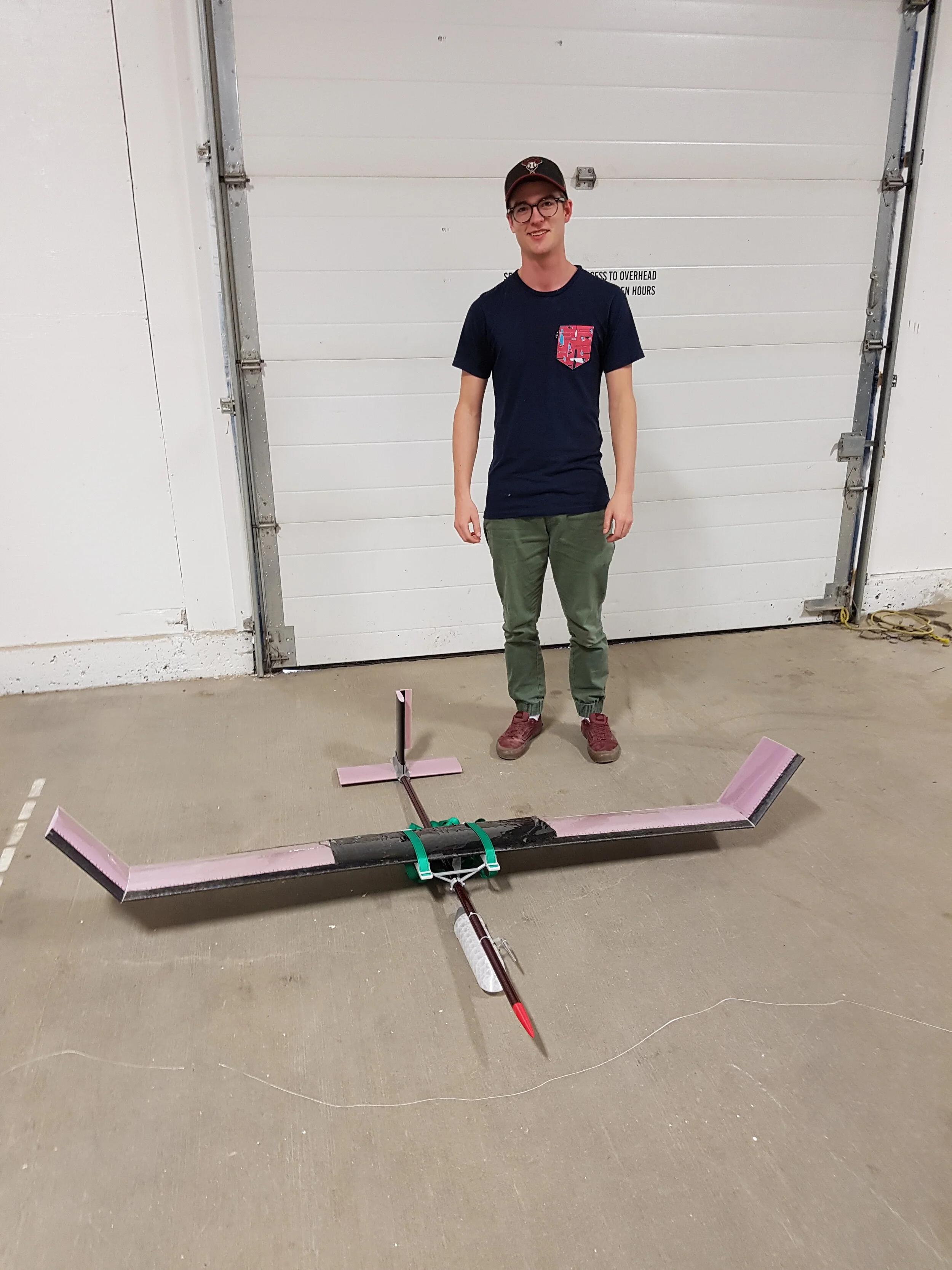
Pictured here is the solid model of the KP-002, the end result after several months of research and experimentation.
After some preliminary literature review, I sat down with Vern and began defining a direction for the project through quality function deployment. This helped to prioritize and split the project into three main subsystems: controls, energy generation, and the kite itself. It was decided that I would provide the most value to KISC by prototyping a kite with an initial control unit.

Fabrication
Strategically located inside a makerspace, I had access to various tools and machinery, including a large format CNC router. Pictured here is the machining of the middle 1.2 meter span of the main wing. The Computer Aided Machining (CAM) and work holding strategies I employed produced a smooth airfoil without seams in about 45 minutes.

Engineering Validation
The structural integrity of the 2 meter span wing was of critical concern, even more so than for a typical aircraft because of its tether. Complicating this further was the use of a foam core wing with varying fiberglass and carbon fiber layers of skin.
Pictured here is a 3-point bending test. While not quite to ASTM-D7264 standards, it did validate my estimate for the flexural modulus of the wing. I estimated the flexural modulus using composite beam theory and manufacturer data. After confirming my methodology was on the right track, I was able to determine an appropriate layup schedule for a desired maximum airspeed.